
")
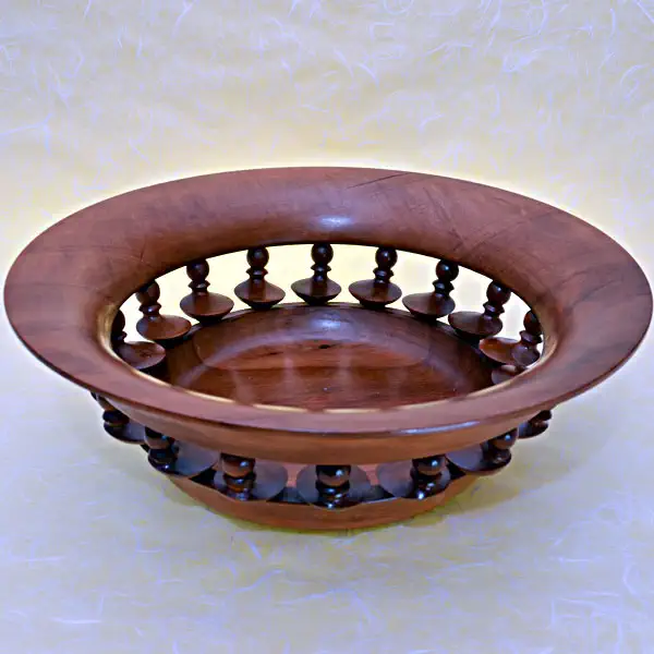 A few years ago I found in a German DIY magazine a step-by-step guide to replicating an award-winning bowl made by an English wood turner, in which the base and rim were connected by a number of interestingly shaped columns with a bent axis of rotation.

")


This project fascinated me so much that on the same day I had a lot of fun making two identically sized columns from a few pieces of scrap wood according to the instructions given. Before I started making a complete bowl like this out of pearwood a few weeks later, I thought through the work steps carefully again and wondered whether anything could be simplified. At that time I had just successfully put my self-made “Eureka” chuck into operation and of course wanted to turn as much of it as possible “on the fly”. Now, of all things, this tedious game of patience got in the way of having to turn these short columns between the trident and the center point. After pondering for a long time about how one could use simple means to build an adapter with which the stop chuck could be attached to the lathe spindle in such a way that bent axes of rotation were created, I finally came up with the idea that offset axes of rotation could be created much more simply and easily reproducibly I only had to provide my chuck with a second threaded hole whose center distance to the first corresponds to the distance between the offset axes of rotation. Since my chuck contained an M10 thread, the smallest possible distance was 11mm, which leaves just a 1mm bar between the holes. Theoretically you could work with this food. Unfortunately, the screwed-on chuck creates a considerable imbalance. The speed cannot be reduced arbitrarily because with offset turning the tool is not engaged throughout the entire revolution and at low speeds the individual blows on the (hand-held) tool are noticeable and very annoying. A precision mechanic friend of mine finally helped me turn a “balancing weight” according to my ideas. Now everything was really a “round thing”. The resulting “offset lathe chuck” is extremely easy to assemble. Switching to the second axis of rotation is done without any measuring or adjustment work, simply by screwing it on and off. The compensating body has to be added in between and left out the other time, depending on which axis of rotation is currently required. It's a lot of fun to work with this food. Without exaggeration, I can say that by using my feed it is possible to save 50% of wood and 75% of time spent on making the sprouts. While the production of the bent rungs according to the original work instructions requires five times re-clamping, a rung could be finished using my method after just one re-clamping. However, practical work has shown that it is definitely worth re-clamping twice. This has the advantage that you can then choose the production position so that the side of the rungs mounted in the shell with the small ball that is visible from above is on the flying side of the workpiece. This gives you more space for clean and dimensionally accurate machining of the spherical shape and allows you to move the tool rest much closer to the workpiece. I think this article is an example of how it's always worth looking for simplifications and improvements instead of following the motto: "We've always done it that way!" and constantly expanding the inventory of small, useful tools . A processing stage that would occur between the trident and the center point when turning the rungs. Re-clamping five times until completion, greater wood consumption and poor accessibility during processing made me look for work advantages.